
HID Conversion DONE! (Pics and info)


Thread Starter
|
Senior Member
Joined: Nov 2007
Posts: 108
From: Aylmer, Quebec, Canada
I bought an aftermarket HID conversion kit for 9006 Low Beam replacement. Cost $100 Canadian. I also bought a Relay Harness to resolve the DRL problem on Canadian Cars. Cost $30. Our DRL is done by sending 9 Volts to the Low Beam headlamp. The relay harness should have taken care of this but I had to add one little modification (a capacitor) to make it work. The reason is that the relay will not fire properly causing the HID lamps to flicker when DRL is running.
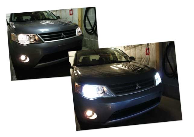
Before Pics, Instructions and After pics below. The result is spectacular! I chose 6000K bulbs. I don't recommend higher to get bluer light, you lose light output.
Before:
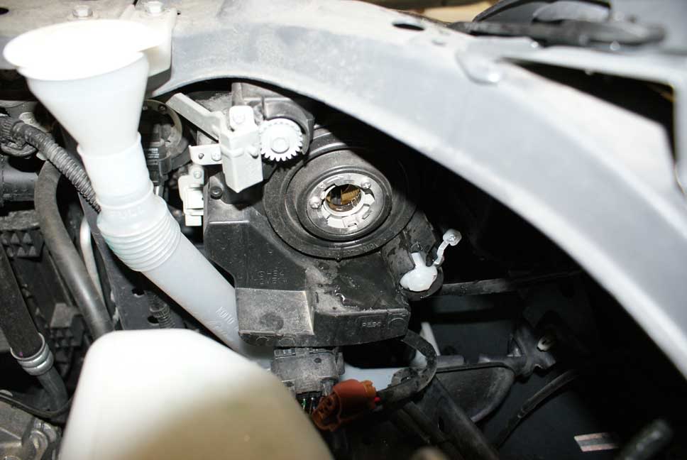
Bulb Removed from Passenger headlamp assembly. Insert your HID lights into the headlamp assemblies. You can loosen the two screws on the retainer if the fit is too tight.
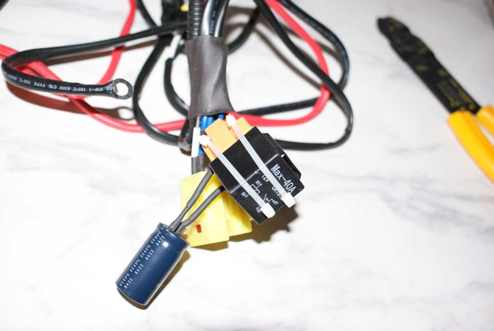
Relay Harness with modification.
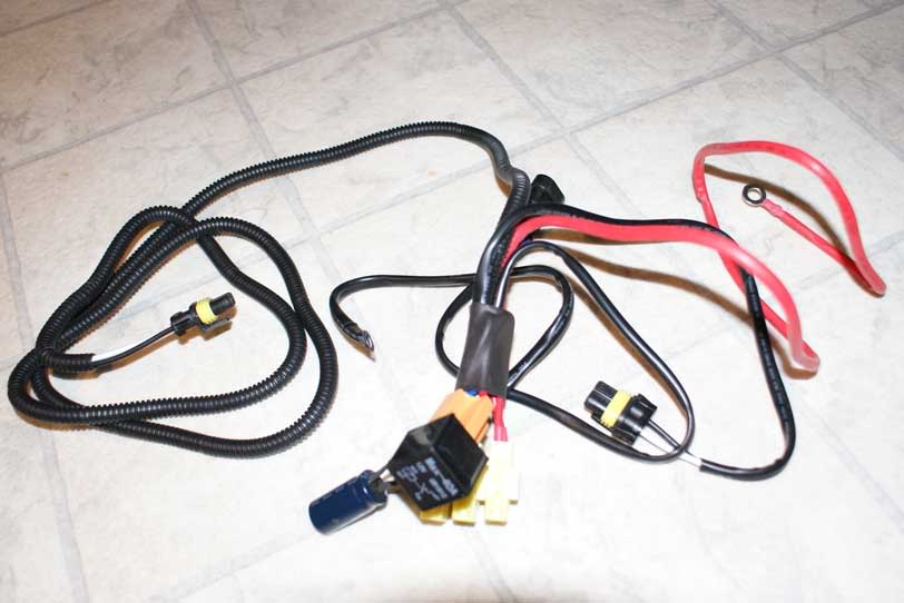
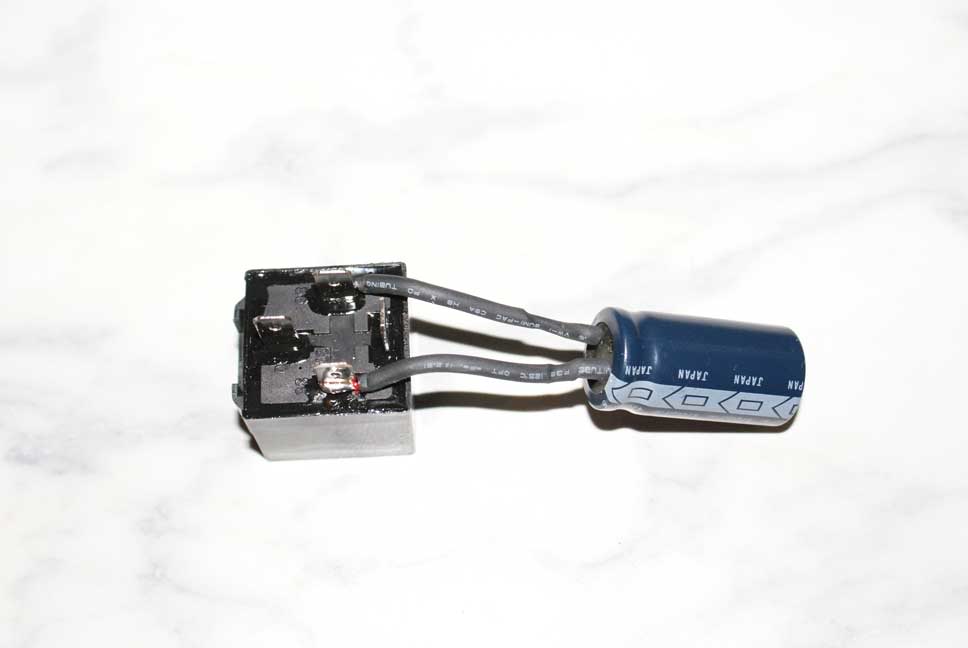
Relay removed showing modification. You must solder a Capacitor in parallel with the coil that activates the relay. If you do not, the relay will click on and off rapidly and this will pulse your HID ballasts and bulbs... BAD. I used a 16V 2500mf capacitor. I wouldn't use anything less. I would actually recommend a 25V capacitor and 2500mf and above.
The relay in the harness is an automotive 12V relay. Typically, the coil is on Pins 85 and 86. You wire the capacitor's positive lead to the the positive post of the relay (usually pin 86), the negative lead to negative post (usually pin 85). I also used a little shrink wrap on the wiring:
Relay back in harness with tie wrap to hold it in solid:
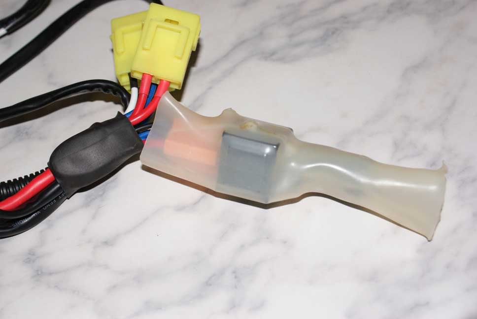
Harness with large shrink wrap to protect the relay and capacitor:
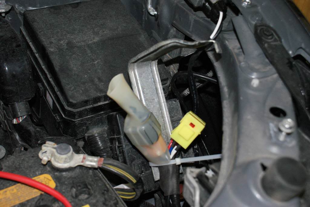
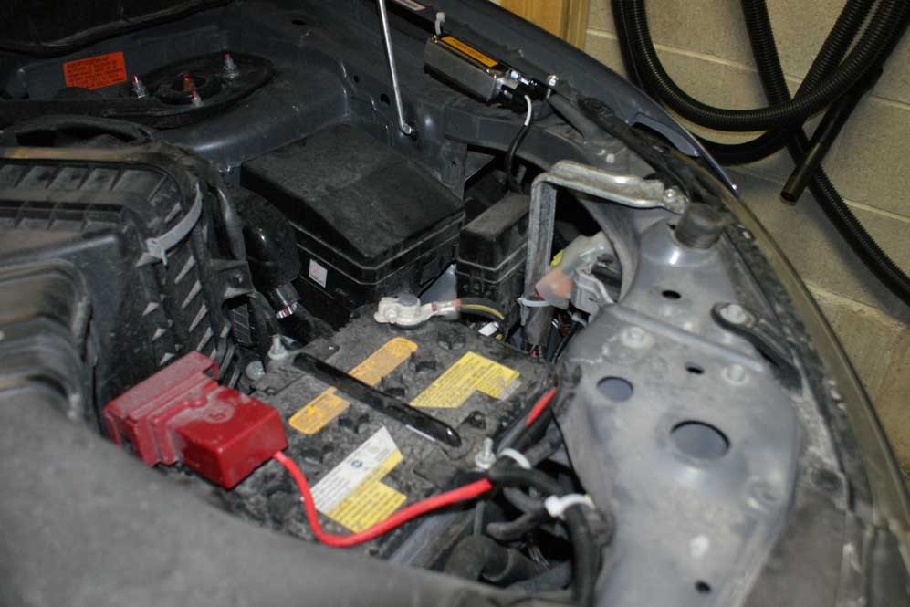
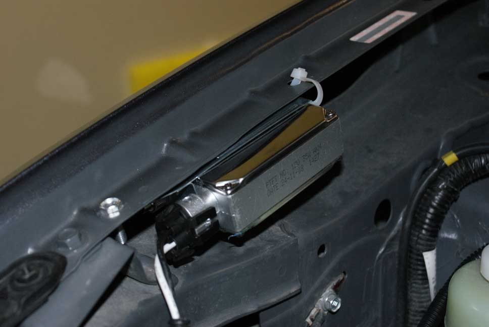
On to the installunder the hood. I tie wrapped the relay harness to the metal bracket that holds an electronic box (black plastic) just behind the drivers headlamp assembly. You will have to remove the bracket to get at the lamp anyway:
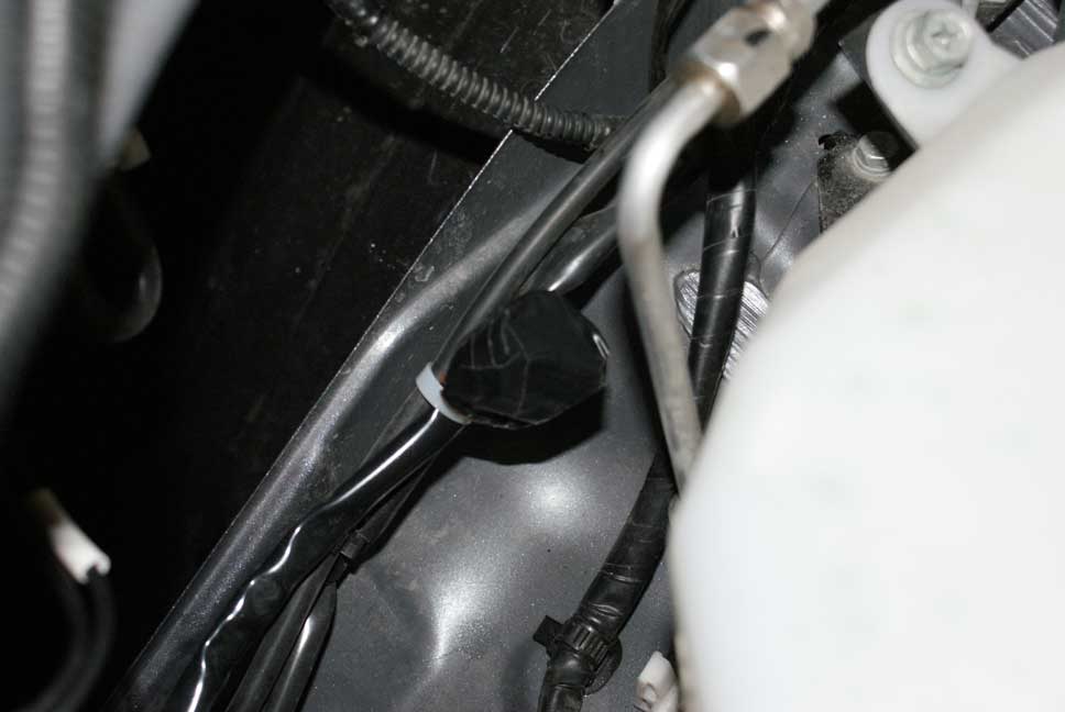
The trigger wire for the relay plugs to the driver side headlamp wiring. Make sure you plug positive to positive, negative to negative. There is no danger but if things don't work, reverse this plug. Use tie wrap to secure the two together:
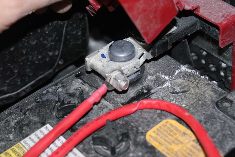
The +12V power that will power your HID ballasts comes from the battery:
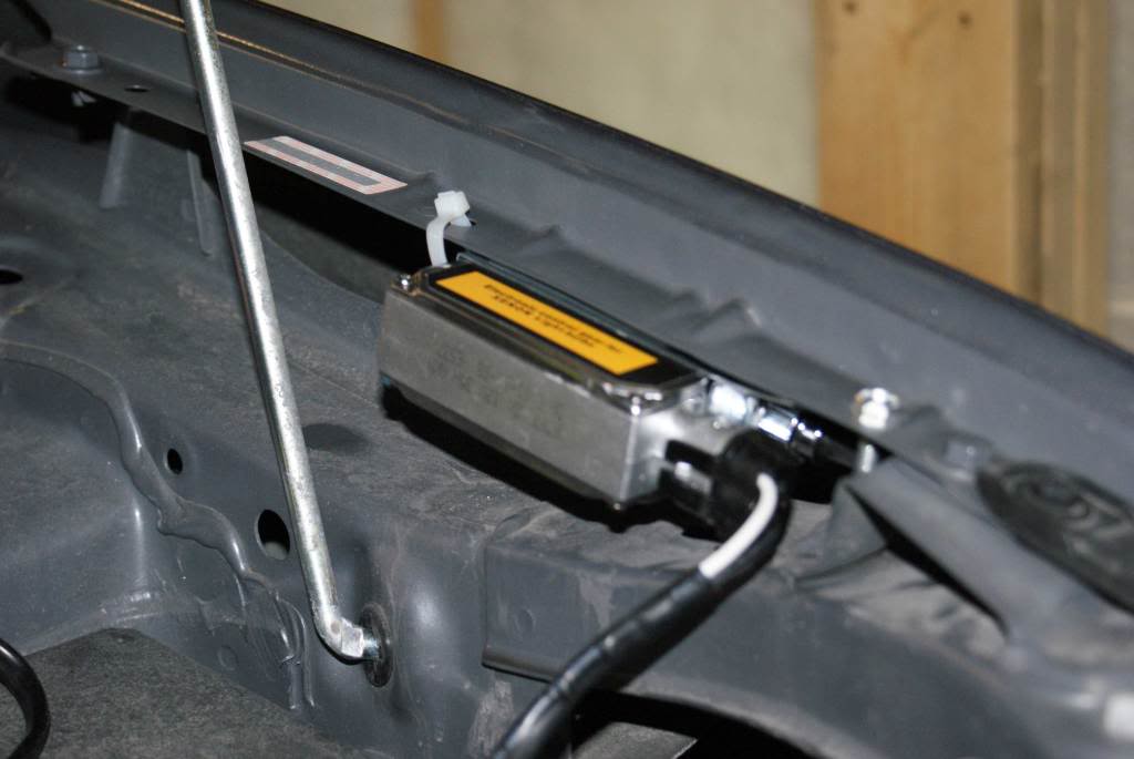
Replace the bracket and electronic box with the relay harness that you tie wrapped to the backside. Use the 10mm screw that holds that bracket down as your grounding point for the relay harness:
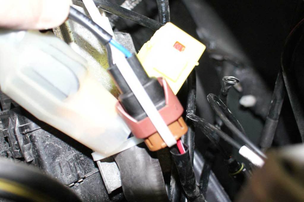
Ensure that you tape off (weather proof) the passenger side headlamp connector. It's not going to be used anymore so tie wrap it to something. The relay harness supplies two lines for bothballasts. The 12V is drawn directly from the battery:
The ballasts fit really nicely below the lip of the fender on both sides. Conveniently, there are holes you can use to secure the ballasts bracket assembly with a nut and bolt on one side and a tie wrap on the other side:
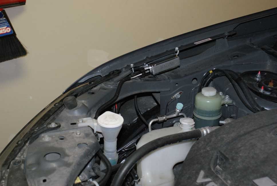
Connect the ballasts to the bulbs that you have already inserted into the headlamp assemblies. Connect the two power lines coming from the relay harness to each ballast. The drivers side ballast power lead is quite short, the passenger side is quite long. I routed the line going to the passenger side in front of the battery, following above the radiator and then to the passenger side. There are many points to secure your wiring with tie wraps along the way. Clean up your install with tie wraps anywhere necessary.
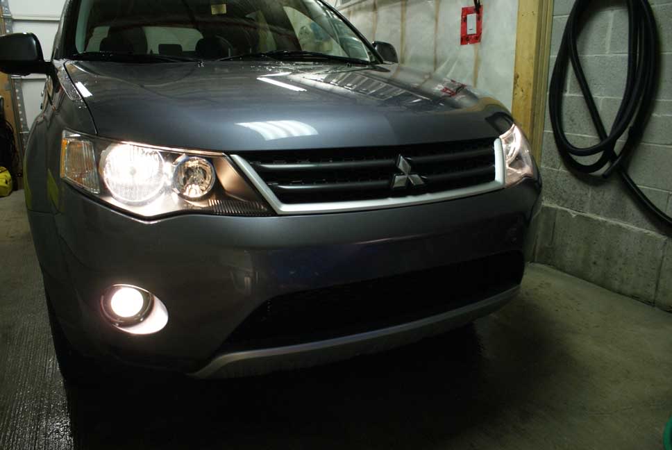
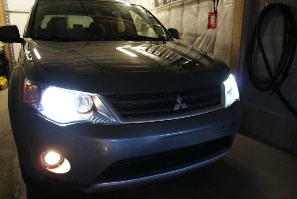
And finally, the finished product!! I tested on the road, and it was absolutely not necessary to readjust the beam heights, they're perfect. Light output is incredible, 3X that of the stock halogens. Stick with 6000K bulbs, anything higher is just silly. I may eventually do the fogs as well, although I like the effect of the two different light temperatures, makes the HID stand out even more.
Before Pics, Instructions and After pics below. The result is spectacular! I chose 6000K bulbs. I don't recommend higher to get bluer light, you lose light output.
Before:
Bulb Removed from Passenger headlamp assembly. Insert your HID lights into the headlamp assemblies. You can loosen the two screws on the retainer if the fit is too tight.
Relay Harness with modification.
Relay removed showing modification. You must solder a Capacitor in parallel with the coil that activates the relay. If you do not, the relay will click on and off rapidly and this will pulse your HID ballasts and bulbs... BAD. I used a 16V 2500mf capacitor. I wouldn't use anything less. I would actually recommend a 25V capacitor and 2500mf and above.
The relay in the harness is an automotive 12V relay. Typically, the coil is on Pins 85 and 86. You wire the capacitor's positive lead to the the positive post of the relay (usually pin 86), the negative lead to negative post (usually pin 85). I also used a little shrink wrap on the wiring:
Relay back in harness with tie wrap to hold it in solid:
Harness with large shrink wrap to protect the relay and capacitor:
On to the installunder the hood. I tie wrapped the relay harness to the metal bracket that holds an electronic box (black plastic) just behind the drivers headlamp assembly. You will have to remove the bracket to get at the lamp anyway:
The trigger wire for the relay plugs to the driver side headlamp wiring. Make sure you plug positive to positive, negative to negative. There is no danger but if things don't work, reverse this plug. Use tie wrap to secure the two together:
The +12V power that will power your HID ballasts comes from the battery:
Replace the bracket and electronic box with the relay harness that you tie wrapped to the backside. Use the 10mm screw that holds that bracket down as your grounding point for the relay harness:
Ensure that you tape off (weather proof) the passenger side headlamp connector. It's not going to be used anymore so tie wrap it to something. The relay harness supplies two lines for bothballasts. The 12V is drawn directly from the battery:
The ballasts fit really nicely below the lip of the fender on both sides. Conveniently, there are holes you can use to secure the ballasts bracket assembly with a nut and bolt on one side and a tie wrap on the other side:
Connect the ballasts to the bulbs that you have already inserted into the headlamp assemblies. Connect the two power lines coming from the relay harness to each ballast. The drivers side ballast power lead is quite short, the passenger side is quite long. I routed the line going to the passenger side in front of the battery, following above the radiator and then to the passenger side. There are many points to secure your wiring with tie wraps along the way. Clean up your install with tie wraps anywhere necessary.
And finally, the finished product!! I tested on the road, and it was absolutely not necessary to readjust the beam heights, they're perfect. Light output is incredible, 3X that of the stock halogens. Stick with 6000K bulbs, anything higher is just silly. I may eventually do the fogs as well, although I like the effect of the two different light temperatures, makes the HID stand out even more.


Thread Starter
|
Senior Member
Joined: Nov 2007
Posts: 108
From: Aylmer, Quebec, Canada
ORIGINAL: mightyOUTTIE
aww nice! hey, you have to mod the relay?
Also can you show me where which slot you put the relay in the fuse box?
aww nice! hey, you have to mod the relay?
Also can you show me where which slot you put the relay in the fuse box?
In Canada, when you start your engine and lower your hand brake, the DRL come on. This is done by sending lower voltage to your low beam lights giving them a half-intensity look. The relay harness is supposed to deal with this by detecting the power coming to the headlamp power supply lead and triggering the automotive relay that passes a full 12V from the battery to the ballasts. However, without the capacitor in parallel, the relay clicks on and off rapidly and flickers your ballasts and bulbs. You definitely don't want this as the ballasts and bulbs won't take that stress. The lower voltage is not the real culprit. The DRL signal is not a constant 9VDCbut rather a sinsusoidal waveform peaking at 12VDC and a frequency of about 60Hz (this is better for the bulb longevity than running them at 9V). This is great for your stock 9006 bulbs but not the coil of the relay. The capacitor smooths this out and allows the relay to trigger properly.
To be clear, when my DRL are running now, I have full intensity in my HID low beams now. There is no more half intensity. So, in essence, my HID run all the time, but they will never flicker.
The relay isnot installed in the fuse box. I bought theDRL relay harness ($30) from the company that sold me the HID kit. The harness is shown in many of the pictures in my post above. It consists of an automotive relay, 3 fuses (1 protecting the 12V coming in, 1 for each ballast), a trigger wire that connects to your drivers side headlamp power supply lead, 2 wires going to the ballasts, 1 12V power supply lead connected to the battery and 1 ground wire that you attach to the chassis. The capacitor that I added is connected in parallel to the coil on pins 85 and 86 of the relay. I soldered it in place and replaced the relay back into the harness connector.
Dan

Senior Member
Joined: Jun 2008
Posts: 274
From:
Beautiful, I was waiting for this to be done, and not for $2000 like some guys did.
A coule things I still need Dek, being as I'm not electrically inclined or savvy whatssoever. I don't want to begin to attempt this project then get stuck along the way...you did a great job alreadywith the step by step.
If you could,
1. List all parts + price
2. Tools you used
3. extra parts (some shrink wrap, ties)
4. Total time and whre you got the kit? I know some kits are good and some are terrible, looks like you got lucky for $100...

Member
Joined: Mar 2008
Posts: 31
From: Canada
Wow, hope I won't be driving towards you in oncoming traffic. You'll be blinding other drivers with the glare. Installing hid's in non-projector housings is not advisable.
Want to know more, see here:
http://www.intellexual.net/hid.html
Want to know more, see here:
http://www.intellexual.net/hid.html

Senior Member
Joined: Sep 2007
Posts: 609
From: Colorado
ORIGINAL: Canuck
Wow, hope I won't be driving towards you in oncoming traffic. You'll be blinding other drivers with the glare. Installing hid's in non-projector housings is not advisable.
Want to know more, see here:
http://www.intellexual.net/hid.html
Wow, hope I won't be driving towards you in oncoming traffic. You'll be blinding other drivers with the glare. Installing hid's in non-projector housings is not advisable.
Want to know more, see here:
http://www.intellexual.net/hid.html
One question dekodan, when parked against a wall (about 10 feet away) what does the light pattern look like?
This is what the OEM HID pattern look like. Has a pretty good cut off.

PS: GOOD JOB on your mod!
Thread Starter
|
Senior Member
Joined: Nov 2007
Posts: 108
From: Aylmer, Quebec, Canada
ORIGINAL: tdford
Well the OEM HID's are not in projector housings, they are in reflector ones as well. Tons of cars have oem hid setups that dont have projector housings. Yes the reflector ones and the hid bulbs that are used are designed to make sure light is not scattered all over the place though...
One question dekodan, when parked against a wall (about 10 feet away) what does the light pattern look like?
This is what the OEM HID pattern look like. Has a pretty good cut off.
PS: GOOD JOB on your mod!
ORIGINAL: Canuck
Wow, hope I won't be driving towards you in oncoming traffic. You'll be blinding other drivers with the glare. Installing hid's in non-projector housings is not advisable.
Want to know more, see here:
http://www.intellexual.net/hid.html
Wow, hope I won't be driving towards you in oncoming traffic. You'll be blinding other drivers with the glare. Installing hid's in non-projector housings is not advisable.
Want to know more, see here:
http://www.intellexual.net/hid.html
One question dekodan, when parked against a wall (about 10 feet away) what does the light pattern look like?
This is what the OEM HID pattern look like. Has a pretty good cut off.
PS: GOOD JOB on your mod!


Thread Starter
|
Senior Member
Joined: Nov 2007
Posts: 108
From: Aylmer, Quebec, Canada
ORIGINAL: ryandlor
Beautiful, I was waiting for this to be done, and not for $2000 like some guys did.
A coule things I still need Dek, being as I'm not electrically inclined or savvy whatssoever. I don't want to begin to attempt this project then get stuck along the way...you did a great job alreadywith the step by step.
If you could,
1. List all parts + price
2. Tools you used
3. extra parts (some shrink wrap, ties)
4. Total time and whre you got the kit? I know some kits are good and some are terrible, looks like you got lucky for $100...
[ol][*]HID Kit $100 (6000K bulbs, don't go higher, digital ballasts)[*]DRL Relay harness $30[*]Shrink wrap and tie wraps ($5)[*]Capacitor : Electrolytic, Polarizedat Radio Shack or local electronics/stereo store 25V (or higher) and 2000uF (or higher) ($2) [/ol]
Tools used:
[ol][*]Philips screw driver[*]10mm ratchet[*]cutters[*]soldering iron (to attach capacitor)[/ol]
Time to install and where to purchase:
2 hours
Kit purchased from local seller in Ottawa. http://www.extremelightz.com