
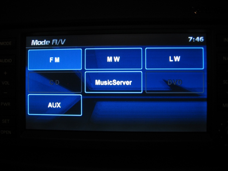
No AUX option on MMCS Mode


Senior Member
Joined: Aug 2007
Posts: 947
From: M�xico
So I understood.
I just need to buy the VTR and it should be OK.
Unbelievable !
for jsrd as I speak sapnish: Muchas gracias jsrd espero pueder ayudarte algun dia.
No se como haceis para encontrar todas estas informaciones sois unos genios !
to rastel69: thanks for the link.
I will tell you about the issue !

I just need to buy the VTR and it should be OK.
Unbelievable !
for jsrd as I speak sapnish: Muchas gracias jsrd espero pueder ayudarte algun dia.
No se como haceis para encontrar todas estas informaciones sois unos genios !
to rastel69: thanks for the link.
I will tell you about the issue !
Saludos

Thread Starter
|
Junior Member
Joined: May 2009
Posts: 14
From: France
Hi,
Well, I'm afraid I have bad news.
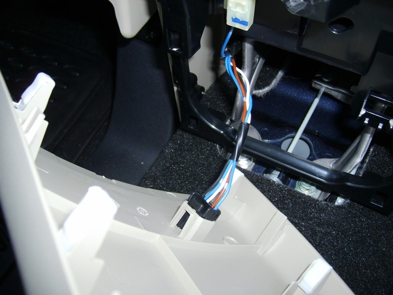
Here you have a picture of the connector which is supposed to be the D123 one.
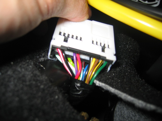
It seems there are too much wires on this connector no ? (18 wires).
Do you have any idea or any explication ? Is that normal ?
Waiting for your point of view.
Well, I'm afraid I have bad news.
Here you have a picture of the connector which is supposed to be the D123 one.
It seems there are too much wires on this connector no ? (18 wires).
Do you have any idea or any explication ? Is that normal ?
Waiting for your point of view.
Senior Member
Joined: Aug 2007
Posts: 947
From: M�xico
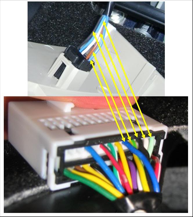
Wow stef48, you removed the D-123 harness, nice. Can you to make one pic from opposite side of harnessr?
Don't worry, all is 0k. D-123 has 24 pines, and 18 wires conected.
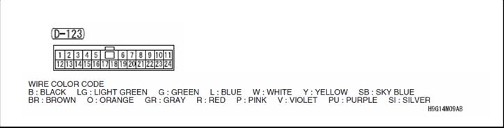
So, this is the order of wires
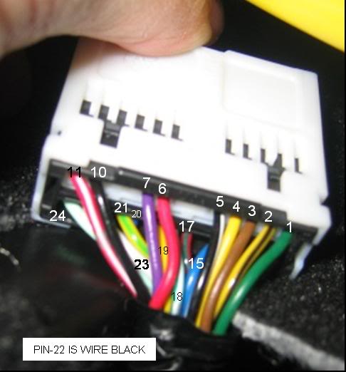
Now, you need to unit in D-123 the next pines to send the signal from AUX inputs to MMCS:
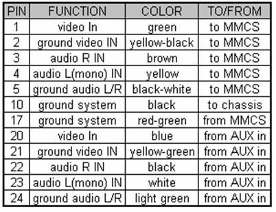
(blue)20-1(green) ~ video IN
(yellow-green)21-2(yellow-black) ~ ground video IN
(black)22-3(brown) audio R IN
(white)23-4(yellow) ~ audio L(mono) IN
(lightgreen)24-5(black-white) ~ ground audio L/R
(red-green)17-10(black) ~ ground system
NOTE: Before you make the unions in D-123, tries to check continuity between C-117 and D-123 (1-20 / 2-21 / 6-22 / 4-23 / 5-24) terminals
Good Luck
Don't worry, all is 0k. D-123 has 24 pines, and 18 wires conected.
So, this is the order of wires
Now, you need to unit in D-123 the next pines to send the signal from AUX inputs to MMCS:
(blue)20-1(green) ~ video IN
(yellow-green)21-2(yellow-black) ~ ground video IN
(black)22-3(brown) audio R IN
(white)23-4(yellow) ~ audio L(mono) IN
(lightgreen)24-5(black-white) ~ ground audio L/R
(red-green)17-10(black) ~ ground system
NOTE: Before you make the unions in D-123, tries to check continuity between C-117 and D-123 (1-20 / 2-21 / 6-22 / 4-23 / 5-24) terminals
Good Luck
Last edited by jsrd; Jun 3, 2009 at 11:47 AM.
Thread Starter
|
Junior Member
Joined: May 2009
Posts: 14
From: France
Hi jsrd,
I have quickly tested the continuity between D123 and the supposed C117:
1- no beep heard but I have to test another time because I'm not sure I did it well.
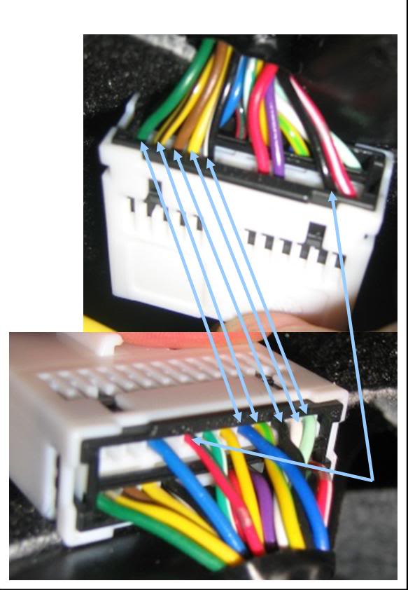
2- Here you have a closer pic of the same connector which is in my car (it's not a pic from my car but it's exactly the same) . Just to show you that the wires for the ground (video ground = brown with silver point or audio ground = blue with silver point) are different that on the D123 connector where as the Video In and Audio In wires (L & R) are the same color that on the D123 connector.
What do you think about the difference of color for the ground wires ?
Is there an other connector some where ?
And there you have the other side of the connector where you could see the others wires.

Thanks for still help me.
I have quickly tested the continuity between D123 and the supposed C117:
1- no beep heard but I have to test another time because I'm not sure I did it well.
2- Here you have a closer pic of the same connector which is in my car (it's not a pic from my car but it's exactly the same) . Just to show you that the wires for the ground (video ground = brown with silver point or audio ground = blue with silver point) are different that on the D123 connector where as the Video In and Audio In wires (L & R) are the same color that on the D123 connector.
What do you think about the difference of color for the ground wires ?
Is there an other connector some where ?
And there you have the other side of the connector where you could see the others wires.
Thanks for still help me.
Senior Member
Joined: Aug 2007
Posts: 947
From: M�xico
Thank's for the pic stef48. I hope that you can do another check for continuty between C-117 and D-123, this is important to be able to continue your project:
About color change in ground wires, this is indicated in the splice points S-047/S106 (VIDEO), S046/S105 (AUDIO), in the wiring diagram, so this situation is normal.
About color change in ground wires, this is indicated in the splice points S-047/S106 (VIDEO), S046/S105 (AUDIO), in the wiring diagram, so this situation is normal.
Thread Starter
|
Junior Member
Joined: May 2009
Posts: 14
From: France
Great news!
The continuity is correct 100% checked!
I have no understood yet how and where the color of the ground wires change but it works.
So I have just to find a way to connect all these wires (and as I want to do something clean I have to prepare a little my solution).
Many thanks jsrd for your very helpfull support.
(If it works, and it should, lot of 4007 or C-Crosser owner we'llbe happy).
To be continued.
Senior Member
Joined: Aug 2007
Posts: 947
From: M�xico
I don't knows about the ground wires change color, but while it just as in wiring diagram, it is what important. . .
Last edited by jsrd; Jun 4, 2009 at 03:26 PM.


Junior Member
Joined: Jun 2009
Posts: 4
From: Italy
Thank you I connected AUX too on my car!!!
I'm italian and I had C-crosser with same problem : no AUX connection.
With your thread I solved my problem.
The important connection is 10 - 17 on D123 to switch on the AUX option on MMCS.
Thank you yet.
ps. sorry for my bad English
I'm italian and I had C-crosser with same problem : no AUX connection.
With your thread I solved my problem.
The important connection is 10 - 17 on D123 to switch on the AUX option on MMCS.
Thank you yet.
ps. sorry for my bad English

